Internet Security Router User
’s Manual
Chapter 10. Configuring VPN
101
Internet
192.168.1.10
ISR1
ISR2
ADSL/Cable Modem
ADSL/Cable Modem
192.168.1.11
192.168.1.12
192.168.1.12
192.168.1.11
192.168.1.10
LAN
192.168.1.1
WAN
123.1.1.123
WAN
212.1.1.212
LAN
192.168.1.1
Mapped to
192.168.11.0
Mapped to
192.168.12.0
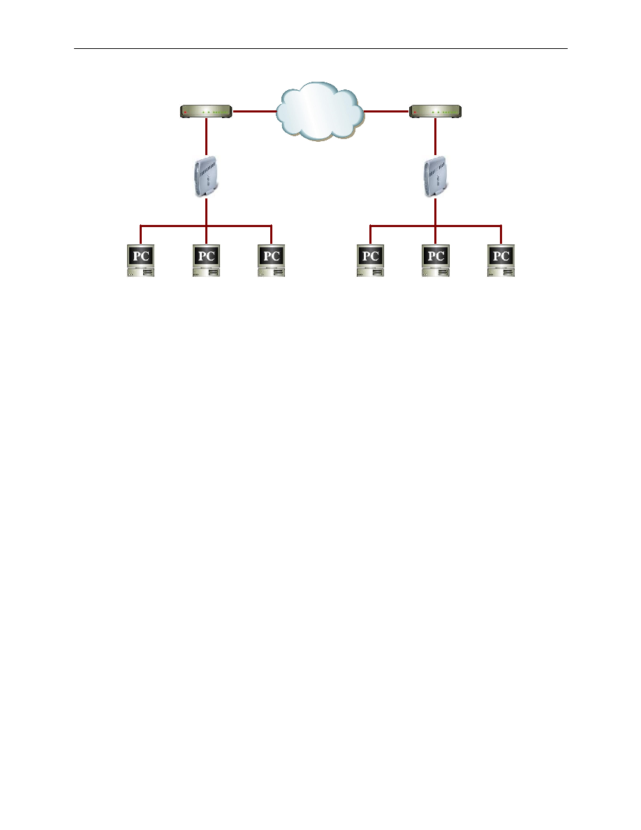
Figure 10.7. Typical Extranet Network Diagram
Both networks behind the ISR1 and ISR2 are 192.168.1.0/255.255.255.0.
To avoid routing problems in such scenario, network IP addresses must be mapped to different ones:
„ Network 192.168.1.0/255.255.255.0 behind ISR1 is translated to 192.168.11.0/255.255.255.0 before
VPN processing.
„ Network 192.168.1.0/255.255.255.0 behind ISR2 is translated to 192.168.12.0/255.255.255.0 before
VPN processing.
The results are:
„ The LAN behind ISR1 would be viewed as 192.168.11. 0/24 by the LAN behind ISR2.
„ The LAN behind ISR2 would be viewed as 192.168.12. 0/24 by the LAN behind ISR1.
The configuration of each of the Internet Security Routers for extranet scenario consists of the following steps:
„ Configure VPN Connection rules.
„ Configure Firewall rules to allow inbound and outbound VPN traffic by performing one-to-one NAT.
„ Configure a Firewall Self Access rule to allow IKE packets into the Internet Security Router.
10.6.2.1 Setup the Internet Security Routers
On ISR1
1.
Configure LAN interface of ISR1 with IP address 192.168.1.1.
2.
Configure DHCP pool with IP addresses from 192.168.1.10 to 192.168.1.110 on ISR1.
3.
Configure WAN interface of ISR1 with IP address 212.1.1.212.
4.
Add a route on ISR1 with gateway as 123.1.1.123.
5.
Save the configuration.
On ISR2
1.
Configure LAN interface of ISR2 with IP address 192.168.1.1.
2.
Configure DHCP pool with IP addresses from 192.168.1.10 to 192.168.1.110 on ISR2.
3.
Configure WAN interface of ISR2 for IP address 123.1.1.123.
4.
Add a default route on ISR2 with gateway as 212.1.1.212.