HUB AND SPOKE VPN
Copyright 2005, ASUSTeK Computer, Inc.
Page
1
HUB AND SPOKE VPN
Release Date: 2005/6/29
1 Introduction
This application note details the steps for creating VPN tunnels based on “hub and spoke” topology between
ASUS Internet Security Routers. All settings and screen dumps contained in this application note are taken from
ASUS Internet Security Routers running firmware 1.1.68A.410. However, the instructions are applicable to newer
firmware as well.
In the "hub and spoke" VPN topology, all branch offices connect to the central office and each office is able to
connect to resources on the central network, as well as other offices, by going through their local VPN gateway to
link to the central office.
Note
It is recommended that you disable firewall initially to simplify the configuration procedure
when setting up “hub-and-spoke” VPN. You can then create proper ACL rules based on
secure requirement in your network.
2 Dynamic IP for All Branch Offices
This topology allows all branch offices to use dynamic IP to construct a fully meshed VPN networks. Note that
only the headquarter requires static IP.
2.1 Network Setup
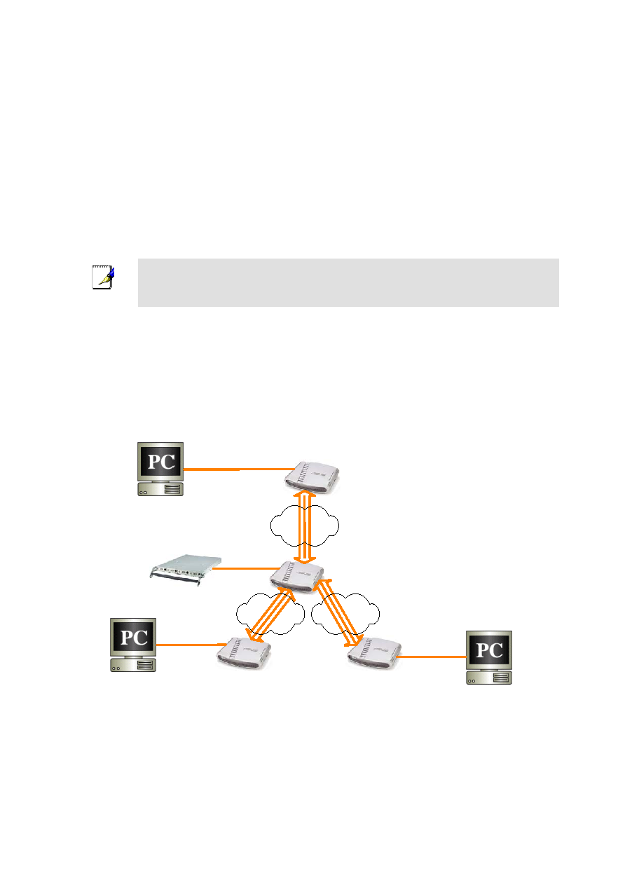
Connect all the devices as indicated in Figure 2.1. You may change the IP address, subnet mask and default
gateway IP address of any device to match your true network environment.
WAN: 66.228.128.1
LAN: 192.168.1.0/24
PC2
192.168.22.10
PC1
192.168.21.10
PC3
192.168.23.10
WAN: dynamic IP
LAN: 192.168.23.0/24
WAN: dynamic IP
LAN: 192.168.21.0/24
WAN: dynamic IP
LAN: 192.168.22.0/24
Branch C
Branch A
Branch B
Headquarter
Server
192.168.1.20
Internet
Internet
Internet
Figure 2.1. Network Toppology Diagram – Dynamic IP for All Branch Offices