GigaX Series L2 Managed Switch User’s Guide
26
4.2
Functional layout
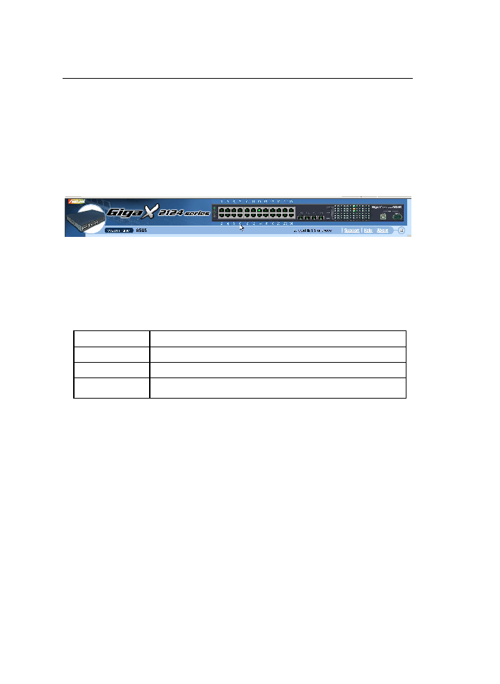
Typical web page consists of three separate frames. The top frame has a
switch logo and front panel as shown in Figures
��
��
��
��. This frame remains on the
top of the browser window all the times and updates the LED status
periodically. See Table 4 for the LED definitions. See Table 5 for the color
status description.
Figure 10. Top frame
Table 4.
Port color description
Port Color
Description
Green port
Ethernet link is established
Black
No Ethernet link
Amber port
Link is present but port is disabled manually or by spanning tree
Clicking on the port icon of the switch displays the port configuration in the
lower right frame.
The left frame, a menu frame as shown in Figure 11, contains all the features
available for switch configuration. These features are grouped into categories,
e.g. System, Bridge, etc. You can click on any of these to display a specific
configuration page.