ASUS PCI-AS300 User's Manual
4
III. INSTALLATION
III.
INST
ALLA
TION
(Layout
/Connect.)
Installation Steps
Before using your computer, you must follow the six steps as follows:
1. Set the card's jumpers
2. Install Expansion Card
3. Connect device cables
4. Configure SCSI ID numbers and termination
5. Setup the oncard SCSISelect Utility if you need to change the defaults
6. Setup the BIOS Software.
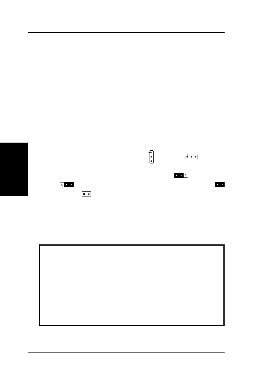
1. Jumpers
Some hardware settings are made through the use of jumper caps to connect jumper
pins (JP) on the card. The jumper settings will be described numerically such as
[----], [1-2], [2-3] for no connection, connect pins 1&2, and connect pins 2&3 re-
spectively. Pin 1 for our cards is always on top
Pin 1
or on the left
Pin 1
when hold-
ing the connectors to the left. A "1" is written besides pin 1 on jumpers with three
pins. The jumpers will also be shown graphically such as
to connect pins
1&2 and
to connect pins 2&3. Jumpers with two pins will be shown as
for short (On) and
for open (Off). For manufacturing simplicity, the jumpers
may be sharing pins from other groups. Use the diagrams in this manual instead of
following the pin layout on the board. Settings with two jumper numbers require
that both jumpers be moved together. To connect the pins, simply place a plastic
jumper cap over the two pins as diagramed.
WARNING: Computer motheboards and components contain very delicate
Integrated Circuit (IC) chips. To protect the motherboard and other compo-
nents against damage from static electricity, you should follow some precau-
tions whenever you work on your computer.
1. Unplug your computer when working on the inside.
2. Hold components by the edges and try not to touch the IC chips, leads, or
circuitry.
3. Use a grounded wrist strap before handling computer components.
4. Place components on a grounded antistatic pad or on the bag that came with
the component whenever the components are separated from the system.