ASUS RS160-E4/PA4
4-17
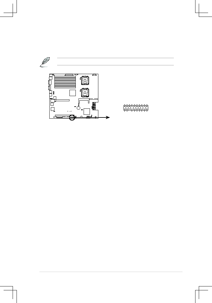
15.. System.panel.connector.(20-1.pin.PANEL1)
This connector supports several chassis-mounted functions.
The system panel connector is color-coded for easy connection.
•.
System.power.LED.(Green.3-pin.PLED)
This 3-pin connector is for the system power LED. Connect the chassis
power LED cable to this connector. The system power LED lights up
when you turn on the system power, and blinks when the system is in
sleep mode.
•.
Hard.disk.drive.activity.LED.(Red.2-pin.IDE_LED)
This 2-pin connector is for the HDD Activity LED. Connect the HDD
Activity LED cable to this connector. The IDE LED lights up or flashes
when data is read from or written to the HDD.
•.
System.warning.speaker.(Orange.4-pin.SPEAKER)
This 4-pin connector is for the chassis-mounted system warning
speaker. The speaker allows you to hear system beeps and warnings.
•.
ATX.power.button/soft-off.button.(Yellow.2-pin.PWRSW)
This connector is for the system power button. Pressing the power
button turns the system on or puts the system in sleep or soft-off mode
depending on the BIOS settings. Pressing the power switch for more
than four seconds while the system is ON turns the system OFF.
•.
Reset.button.(Blue.2-pin.RESET)
This 2-pin connector is for the chassis-mounted reset button for system
reboot without turning off the system power.
®
DSBF-DE/1U System panel connector
PANEL1
MLED
-
GN
D
NC
POWERBTN#
+5
V
GN
D
GN
D
NC
POWERLED+
IDELED
+
NC
IDELED
-
POWERLED- MLED
+
NMIBTN
#
GN
D
RESETBTN
#
SPKROUT
GN
D