Chapter 4: Motherboard information
4-16
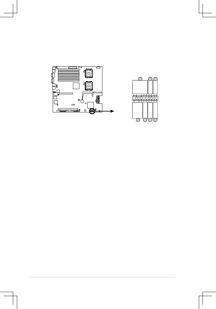
14.. Auxiliary.panel.connector.(20-pin.AUX_PANEL1)
This connector is for additional front panel features including front panel SMB,
locator LED and switch, chassis intrusion, and LAN LEDs.
1.. Front.panel.SMB.(6-1.pin.FPSMB)
These leads connect the front panel SMBus cable.
2.. LAN..activity.LED.(2-pin.LAN1_LED,.LAN2_LED)
These leads are for Gigabit LAN activity LEDs on the front panel.
3. Chassis.intrusion.(4-1.pin.CHASSIS)
These leads are for the intrusion detection feature for chassis with
intrusion sensor or microswitch. When you remove any chassis
component, the sensor triggers and sends a high-level signal to these
leads to record a chassis intrusion event.
4.. Locator.LED.(2-pin.LOCATORLED1.and.2-pin.LOCATORLED2).
These leads are for the locator LED1 and LED2 on the front panel.
Connect the Locator LED cables to these 2-pin connector. The LEDs
will light up when the Locator button is pressed.
5.. Locator.Button/Swich.(2-pin.LOCATORBTN).
These leads are for the locator button on the front panel. This button
queries the state of the system locator.
®
DSBF-DE/1U Auxiliary panel connector
AUX_PANEL1
I2C_4_D
AT
A#
LOC
AT
ORLED1+
+5VSB
LOC
AT
ORLED1-
LAN1_LINK
LOC
AT
ORBTN
#
LAN1_AC
T
GN
D
+5VS
B
I2C_4_CLK#
GND
GN
D
LAN2_AC
T
LOC
AT
ORLED2-
LAN2_LINK
LOC
AT
ORLED2+
CASEOPEN
PIN1
NC
1
2
2
5
4
3
4