Chapter 2: Hardware setup
Chapter 2: Hardware setup
Chapter 2: Hardware setup
Chapter 2: Hardware setup
Chapter 2: Hardware setup
2-16
2-16
2-16
2-16
2-16
2.7.1
2.7.1
2.7.1
2.7.1
2.7.1
Motherboard
Motherboard
Motherboard
Motherboard
Motherboard
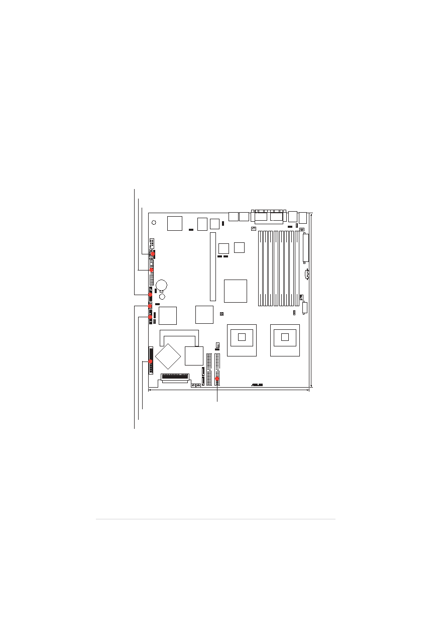
The following illustration describes the cables for the specific connectors
on the motherboard.
AMI
8Mb
FWH
KBPWR1
J2
A
TXPWR1
S
ATA
1
CPU_F
AN2
®
FM_CPU2
SEC_IDE
FLOPPY1
AT
I
RAGE
XL
VGA
Controller
SCSIA1
BUZZ1
35
68
34
1
DDR2
DIMM_A1
(64/72
bit,
240-pin
module)
COM2
Super
I/O
PCIX1
(64-bit,
133MHz
3V)
CR2032
3V
Lithium
Cell
CMOS
Power
P
ANEL1
FRNT_F
AN1
mPGA 604
NCL-DSR1
PS/2
T:
Mouse
B:
Keyboard
USB1
USB2
COM1
PARALLEL PORT
VGA1
RJ-45
(LAN-1)
RJ-45
(LAN-2)
DDR2
DIMM_B1
(64/72
bit,
240-pin
module)
DDR2
DIMM_A2
(64/72
bit,
240-pin
module)
DDR2
DIMM_B2
(64/72
bit,
240-pin
module)
DDR2
DIMM_A3
(64/72
bit,
240-pin
module)
DDR2
DIMM_B3
(64/72
bit,
240-pin
module)
DDR2
DIMM_A4
(64/72
bit,
240-pin
module)
DDR2
DIMM_B4
(64/72
bit,
240-pin
module)
mPGA 604
33cm
(13in)
30.5cm (12in)
PRI_IDE
SCSIB1
FRNT_F
AN2
S
ATA
2
A
TX12V1
CPU_F
AN1
FM_CPU1
Intel
ICH5R
Adaptec
AIC-7902W
Intel
E7520
MCH
BMCCONN1
PSUSMB1
BPSMB1
Intel
PXH
Intel
PXH
AUX_P
ANEL1
HDLED1
SCSI_EN1
USB34
USBPW34
CLR
TC1
VGA_EN1
RECPVER
Y1
LAN1_EN1
LAN2_EN1
Broadcom
BCM5721
Broadcom
BCM5721
SB_PWR1
REAR_F
AN1
REAR_F
AN2
USBPW12
SMBus cable to SCSI BP board
Floppy disk cable to SCSI BP board
LED cable to front panel board
SCSI cable to BP board
20-pin front panel cable to front panel board
USB 2.0 cable to front panel board
IDE cable to optical drive