23
IV. Hardware Setup
IV
.Hardware
Setup
AP 3000 Hardware Reference Guide
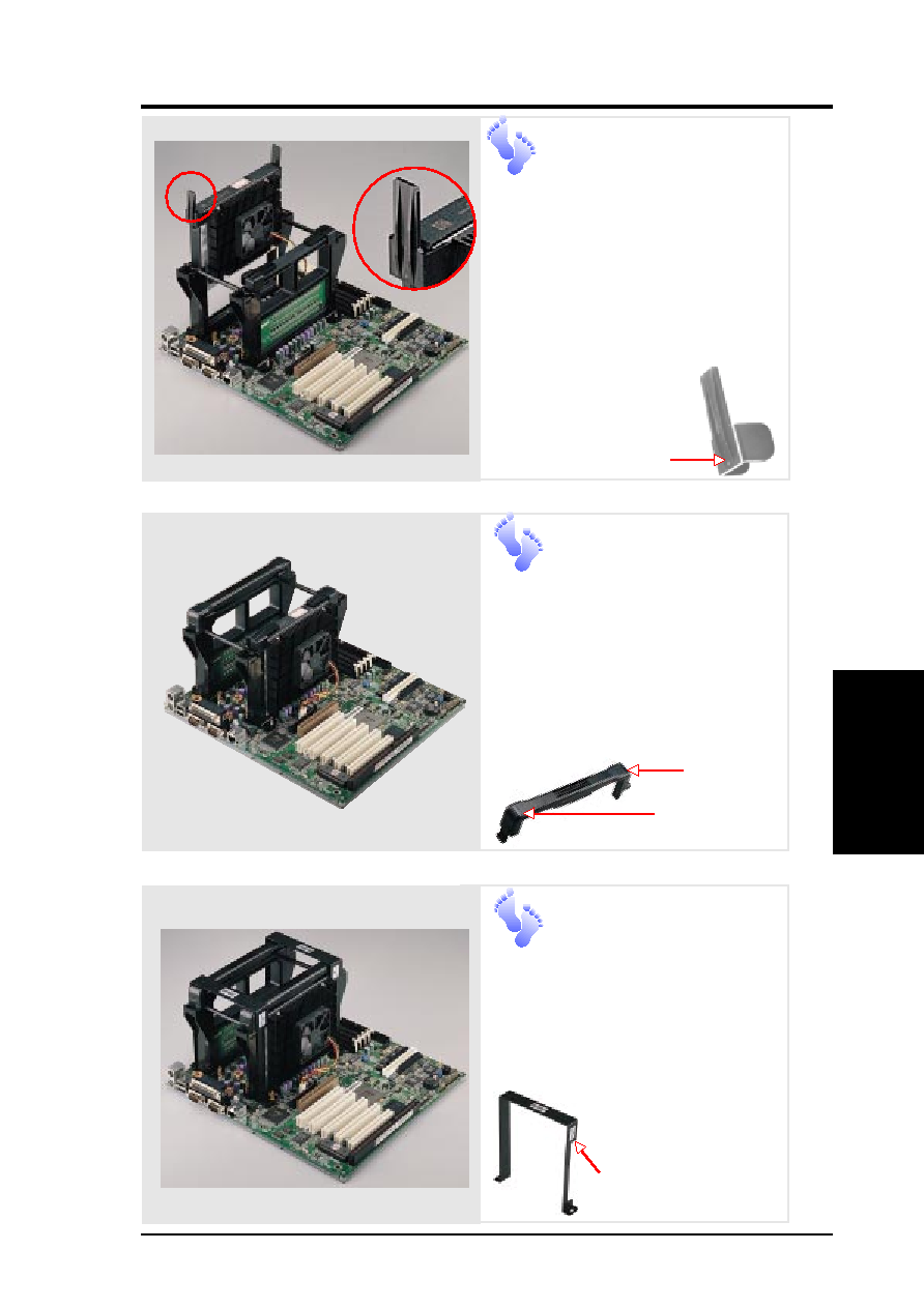
Install Retention
Mechanism
Frame
A metal frame is used accross both
retention mechanisms. After install-
ing the frame, four captive nuts
should be tightened on the feet of the
frame to the screws pro-
truding from the reten-
tion mechanisms.
Sticker (facing
the CPU fan)
CPU
Install Cartridge
Lifters
Each Xeon processor requires two
lifters in order to allow safe removal
of the processor. The lifters clamp
on to the cartridge on the two holes
at the top of each corner.
For the lock bar, there is a left and a
right side. The left side has a single
dot and the right side has
two dots (when holding
the motherboard with the
ATX connectors to the
left).
Single Dot
Install Retention
Mechanism Cap
The cap must go in from the left side
first (with the ATX connectors to the
left). The left side has one dot, while
the right side has two dots. The right
end of the cap enters the retention
mechanism and a click is heard as
it snaps in place.
Two Dots
Single Dot