20
AP7500 Hardware Reference Guide
II.
Components
Hot-Swap
Connector
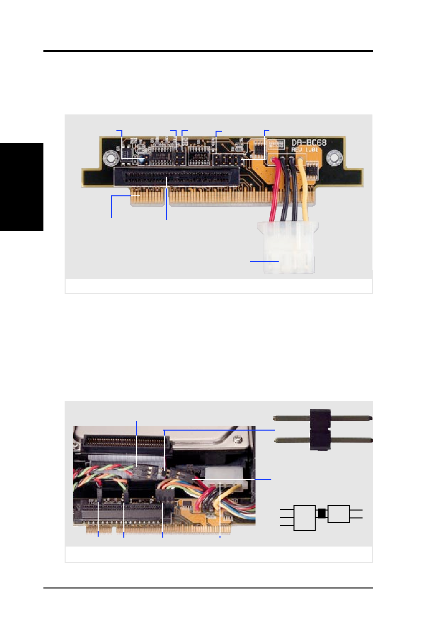
Hot-Swap Tray Connector Board
The connector board is mounted on the hot-swap tray to interface with the
SCSI backplane in the chassis. The connector board combines all the signal
and power into one docking connector for a simple hot-swap unit.
Hot-Swap Tray Rear Connections
KEY: These 2 pins connect to the keylock on the tray’s front panel to turn on
and off the drive’s power.
PLED: These 2 pins connect to the power LED on the tray’s front panel to
show when the connector board receives power.
SCSI_ID: These 8 pins connect to the hard disk drive’s SCSI address pins
to set the SCSI ID number of the hard disk drive.
SLED & ALED: These two wires are connected as illustrated below.
Hot-swap tray connector board parts
Hard Disk Drive
Power Connector
Wide SCSI
Connector
Hot-Swap Tray
Docking Connector
KEY
ALED_IN
(not used)
SCSI_ID
SLED
(not used)
PLED
Hot-swap tray rear connections (Seagate HD)
KEY PLED
SCSI_ID
Power
from hard disk drive’s 2 pin
activity LED (ALED wire)
from tray’s front panel 3 pin
activity LED (SLED wire)
Green
Black
Red
SLED
(wire)
Red
Black
ALED
(wire)
Bridge
Connector Bridge for LED
II. System Components