AP7500 Hardware Reference Guide
19
II.
Components
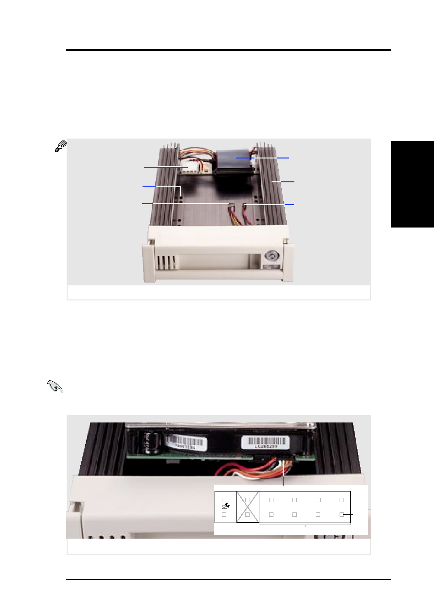
Hot-Swap
T
ray
Hot-Swap Tray Front Connections
The hot-swap tray provides wires for connecting the activity LED, power
LED, SCSI ID, power, and SCSI signal. Connect the 8 pin connector to the
SCSI Address pins according to the colors shown. Connect the 2 pin con-
nector to the activity signal pins according to the colors shown.
IMPORTANT: The following is only an example. Always consult your
hard disk drive documentation or labels for the exact wiring specific to your
hard disk drive make and model.
Hot-Swap Tray Usage
Each hot-swap tray provides an aluminum carrier for a single SCSI hard
disk drive with a maximum height of 1 5/8 inch, width of 4 inches, and
length of 6 inches. The aluminum tray provides protection and maximum
heat dissipation for almost all types of high speed SCSI disk drives. The
provided cables and wires connect to the SCSI hard disk drive and screws
are needed to secure the tray to the bottom of the SCSI hard disk drive.
Hot-swap tray SCSI ID & activity LED wires connected (Seagate HD)
1
2
4
8
Activity
Signal
Blue
Black
White
Yellow
Green
Brown
Red
Red
Black
Orange
SCSI Address (ID#)
Pin 1
Unused
Seagate Cheetah (ST34501W) side opposite power & SCSI
Pin 2
II. System Components
Hot-swap tray and its connectors
SCSI Cable
Power Connector
Activity LED
(ALED)
SCSI ID
Aluminum Tray
Screw Holes