ASUS ASMM User’s Manual
8
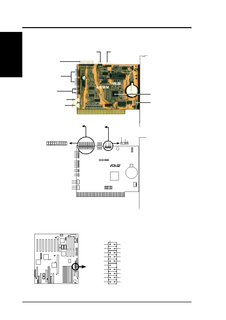
I. ASUS ASMM
Motherboard Server Connector
Server Connector
(NC)
CPU2 TH
Ext SMI#
CPU1 TH
(NC)
Ground
(NC)
(NC)
(NC)
TH REFV
+3Volt Standby
Keylock
SMB Data
SMB Clock
Power LED
(NC)
(NC)
Reset
(NC)
Pin 1
Photo Sensor
Server Connector
CPU 1 Fan
Chassis Fan
CPU 2 Fan
LM78
Hardware
Monitor
JP6
JP4
JP5
8-bit ISA Connector
CR2032
3V Button
Cell Battery
R
Battery Power (
≤10µA)
Intrusion Signal
Ground
1
11
10
20
NC
NC
NC
NC
NC
NC
NC
NC
Ground
CPU1
TH
CPU2
TH
Ext
SMI#
Power
LED
SMB
Clock
SMB
Data
+3V
Standby
Keyboard
Lock
TH
REFV
Reset
RSTCON_MB
RSTCON_C
KLOCK_MB
KLOCK_C
Automatic Server Restart
Period Selection
JP7
Chassis Intrusion
Selection
TO MOTHERBOARD
SERVER
CONNECTOR
TO MOTHERBOARD
EXTERNAL
MICRO-SWITCH
I.ASUS
ASMM
Parts/Layout
ASUS ASMM System Monitoring Module
Key Unlock
Signal Connectors
RESET Signal
Connectors
Hardware Monitor
Chassis Fan Connector
CPU1 Fan Connector
CPU2 Fan Connector
Server Monitor
Signal Connector
(TO MOTHERBOARD
SERVER CONNECTOR)
Minimum Server Monitor
Signal Connector
Chassis Connector
(TO MOTHERBOARD
EXTERNAL MICRO-SWITCH)