Chapter 2: Hardware setup
2-6
2.5
System interface board
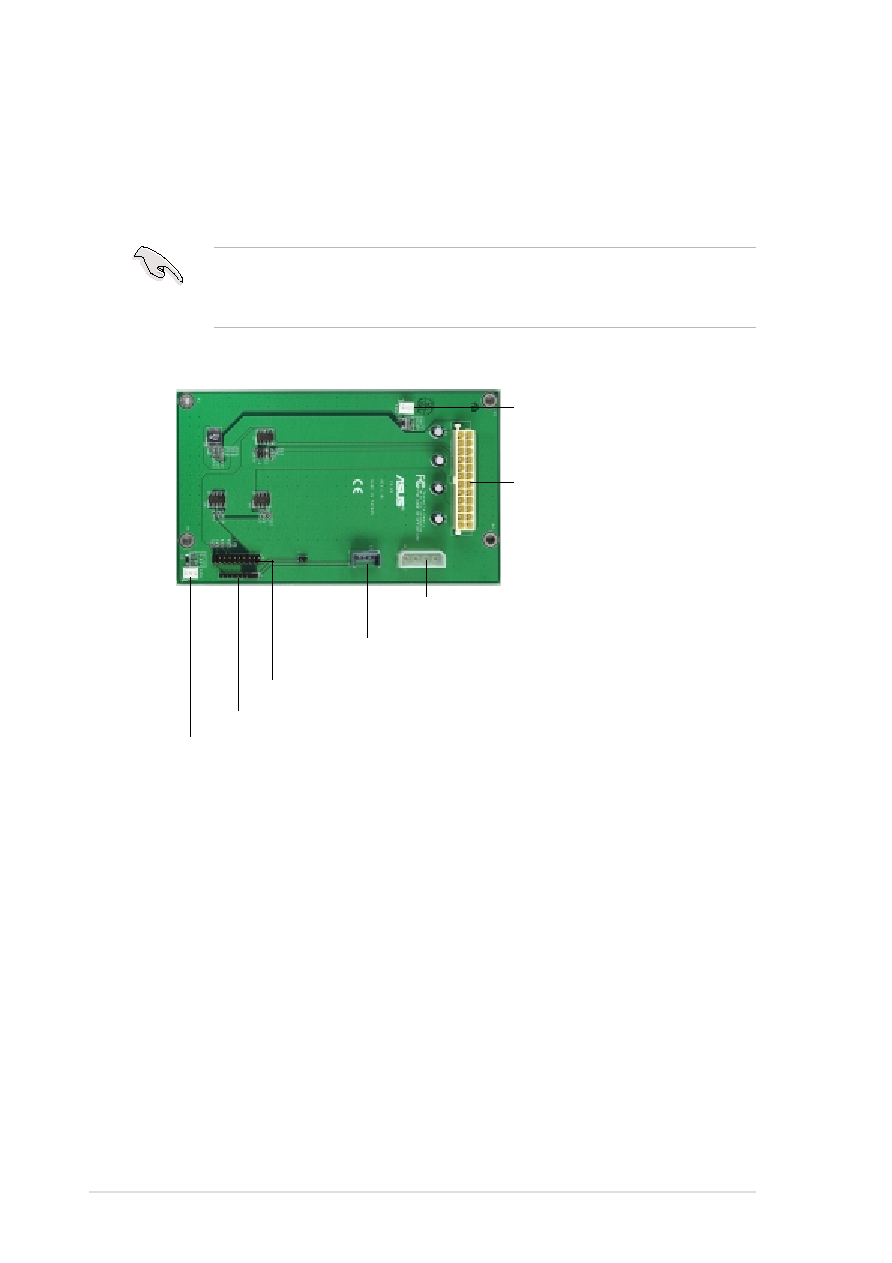
The system interface board interconnects the backplane boards, power
supply, cooling fans, and the DA3100 controller. Refer to the illustration
below for the specific cables connected to the interface board.
All the cables are already connected when you receive the system.
You do not need to disconnect the cables when installing drives or
creating a RAID configuration.
24-pin power connector
(connect P1 plug from power supply)
FAN1 connector
(connect fan cable from
12-cm system blower)
Power connector
(to left power connector on DA3100 controller)
SMBus connector
(to I2C connector on DA3100 controller)
FAN2 connector
(to 8-cm system fan on the PCI cage)
J2 (to power button on the front panel)
J1 (to SMB In/Out bottom pins on left backplane board)