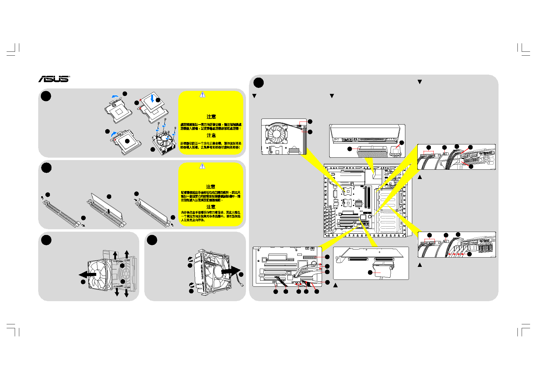
AP1720-E2 Server System
1. Lift the socket lever and push it to
the other side.
2. Position the CPU above the socket.
Match the marked corner of the CPU
and the socket
3. Insert the CPU.
4. Lift the socket lever and push it to
the other side to secure the CPU.
5. Apply thermal grease on top of the
CPU.
6. Install the CPU fan and heatsink.
Memory installation
15-100517710
Cable connections
A
B
CPU installation
CAUTION
The CPU fits only in one correct orientation.
DO NOT force the CPU into the socket to
prevent bending the pins and damaging the
CPU!
CAUTION
A DDR DIMM is keyed with a notch to fit in
only one direction. DO NOT force a DIMM
into a socket to avoid damaging the DIMM.
1. Press the
retaining clips
outward.
2. Align a DIMM on the
socket by matching the
DIMM notch on the socket
break.
3. Insert the DIMM into the
socket until the retaining
clips snap back in place.
Copyright © 2004 ASUSTeK COMPUTER INC. All Rights Reserved.
C HDD fan removal
1. Press the fan case
hooks outward.
2. Remove the HDD fan
from the case.
3. Refer to the system
user guide for
details.
E
Optical drive
1. Signal cable (to the SEC_IDE connector
on motherboard)
2. Power cable (4-pin plug from the
power supply unit)
Technical Support Information: Asia-Pacific
+886-2-2890-7123 • United States
+1-502-995-0883 • Germany/Austria
+49-2102-95590 • Middle East/North Africa
+9714-283-1775
Visit us at:
www.asus.com/products/server
E1856
1
4
1
6
1
2
3
3
1
1
2
Chassis fan removal
1
1
2
2
4
3
D
1. Pull the lock hooks
of the chassis fan
case upward.
2. Remove the chassis
fan from the case.
3. Refer to the User
Guide for details.
3. Floppy disk drive signal cable
(to FDD signal connector)
4. Optical disk drive signal cable
(to ODD signal connector)
5. ATX power cable (24-pin power plug
from the power supply unit)
6. Chassis fan cable (hidden)
7. IEEE 1394 cable (to IEEE 1394
connector on the front I/O board)
8. SMBus cable (to SMBus connector
on backplane, if any)
9. Panel cable (to various chassis front
panel connectors)
10. SATA signal cables (7-pin cables
connected to the SATA connectors
on the SATA backplane. Available on
AA4 models only.)
Motherboard
1. CPU fan cable
2. Power cable (8-pin ATX 12V power plug
from the power supply unit)
SCSI card (On AS4/AS8 models)
1. SCSI cable (to the top 68-pin SCSI connector
on the first SCSI backplane)
1
2
1
2
1
SATA backplane (On AA4 models)
1. Power cables (two 4-pin power plugs
from the power supply unit)
2. HDD fan cable
3. SMBus cable (from the SMBus connector
on the motherboard)
4. SATA signal cables (from the SATA connectors
on the motherboard.
3
4
1
2
7
8
10
9
6
10
4
3
5
5
Lower SCSI backplane
(On AS8 models with cascade configuration)
1. Power cables (two 4-pin power plugs
from the power supply unit)
2. HDD fan cable
3. SMBus cable (from the SMBus connector
on the upper SCSI backplane)
4. SMBus cable (from the SMBus connector
on the power supply)
5. SCSI signal cable (from the second SCSI
connector on the upper SCSI backplane)
Upper SCSI backplane
(On AS4/AS8 models)
1. Power cables (two 4-pin power plugs
from the power supply unit)
2. HDD fan cable
3. SMBus cable (from the SMBus connector
on the motherboard)
4. SMBus cable
AS4 models:
Connects the SMBus connector
on the power supply
AS8 models:
Connects the SMBus connector
on lower SCSI backplane)
5. SCSI signal cable (from the SCSI card connector)
3
2
5
4
1