2-33
ASUS AP1720-E2 barebone server
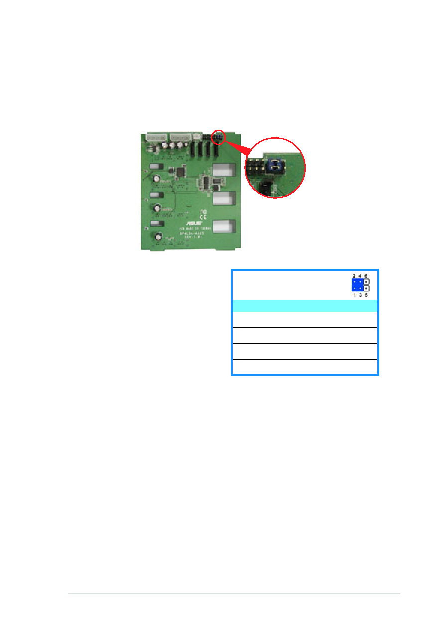
SATA backplane jumper settings and HDD ID assignments
The 6-pin jumper J1 allows you to define your desired SATA configuration.
The picture below shows the location of jumper J1 with pins 1-3 and 2-4
shorted.
Refer to the table for the jumper
settings and the appropriate ID# for
each SATA HDD bay.
J1 setting
(1-3 shorted, 2-4 shorted)
Device
SATA BP ID
Drive Bay 1
CON2
Drive Bay 2
CON4
Drive Bay 3
CON6
Drive Bay 4
CON8