Chapter 2: Hardware setup
2-26
2.9.2 SATA backplane connections
The SATA backplane has four 15-pin SATA connectors to support Serial
ATA hard disks. The backplane design incorporates a hot swap feature to
allow easy connection or removal of SATA hard disks. The LED on the
backplane connect to the front panel LED to indicate HDD status. See
section “1.6 LED information” for details.
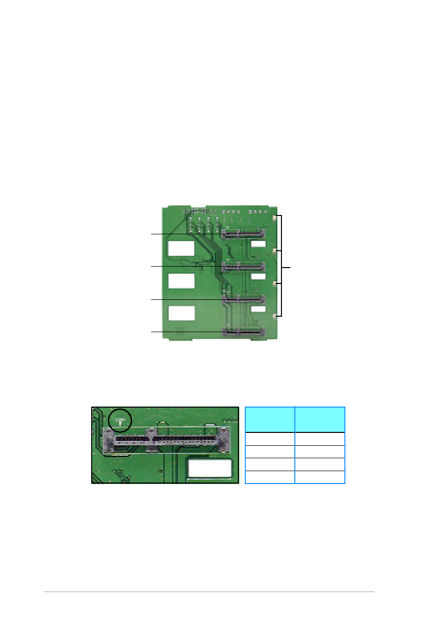
Front side
The front side of the SATA backplane faces the front panel when installed.
This side includes four SATA connectors for the hot swap drive trays.
Drive status LEDs
Disk drive 1
Disk drive 2
Disk drive 3
Disk drive 4
Each SATA connector is labeled (CON1, CON3, CON5, CON7) so you can
easily determine their counterpart connectors at the back side of the
backplane. Refer to the table below for reference.
Connector
Back side
label
connector
CON1
CON2
CON3
CON4
CON5
CON5
CON7
CON6