ASUS PCI-DA2100 Application Note
6
2.2 Main Board BIOS Setting
Put DA2100 in PCI Slot 1, then IRQ number is automatically assigned. If you want to
assign IRQ number by manual, please use System BIOS / PCI and PnP Configuration.
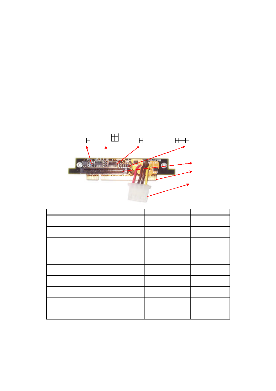
2.3 Connection of Hard Disk Drives with ASUS SCSI Back Panel Board
2.3.1 Prepare Hard Disk Drives and connect to mobile rack
a) If you want to adjust the ID# on Back Panel Board, please connect HDD ID
jumper to SCSI_ID connector.
b) Hard Drive terminator must be disabled.
c) After connect the ID line, R/W LED, put the HDD into the Mobile Rack.
Items
Functions
Cables Uses
Connect To
Golden Finger
Bus of Slot Card
None
DA-BP4-1S
Power Cable
Power of SCSI drive
None
SCSI drive
SCSI connector
Connector of wide SCSI
68-pin wide SCSI
cable
DA-BP4-1S
SCSI_ID(8-pin)
SCSI ID could be managed
from DA-BP4-1(S), refer to Fig:
3-28
SCSI_ID cable, 8-wire,
ID jumper of
SCSI drive.
*Be sure the target
SCSI ID is in the
right order.
ALED_IN(2-pin)
Jumper of device accessing
ALED_IN cable, 2-
wire, (Red/Black)
Access jumper of
SCSI drive
PLED (3-pin)
Power LED
PLED cable, 3-wire,
(Orange/Black/Green)
Light-1 of Drive
Bay
SLED (3-pin)
Status LED
SLED cable, 3-wire,
(Green/Black/Red)
Light-2 of Drive
Bay
KEY (2-pin)
Insure the SCSI drive power has
been off while Key Lock of
Drive Bay being opened. To
protect device during hot-swap.
KEY cable, 2-wire,
(Black/Red)
Key Lock of Drive
Bay
SCSI_ID
ALED_IN
SLED
KEY
PLED
Golden Finger
Power Cable
SCSI Connector