ReportNo. 019L036E
Page : 12 of 48
Version:1.0
2.3.
Limits
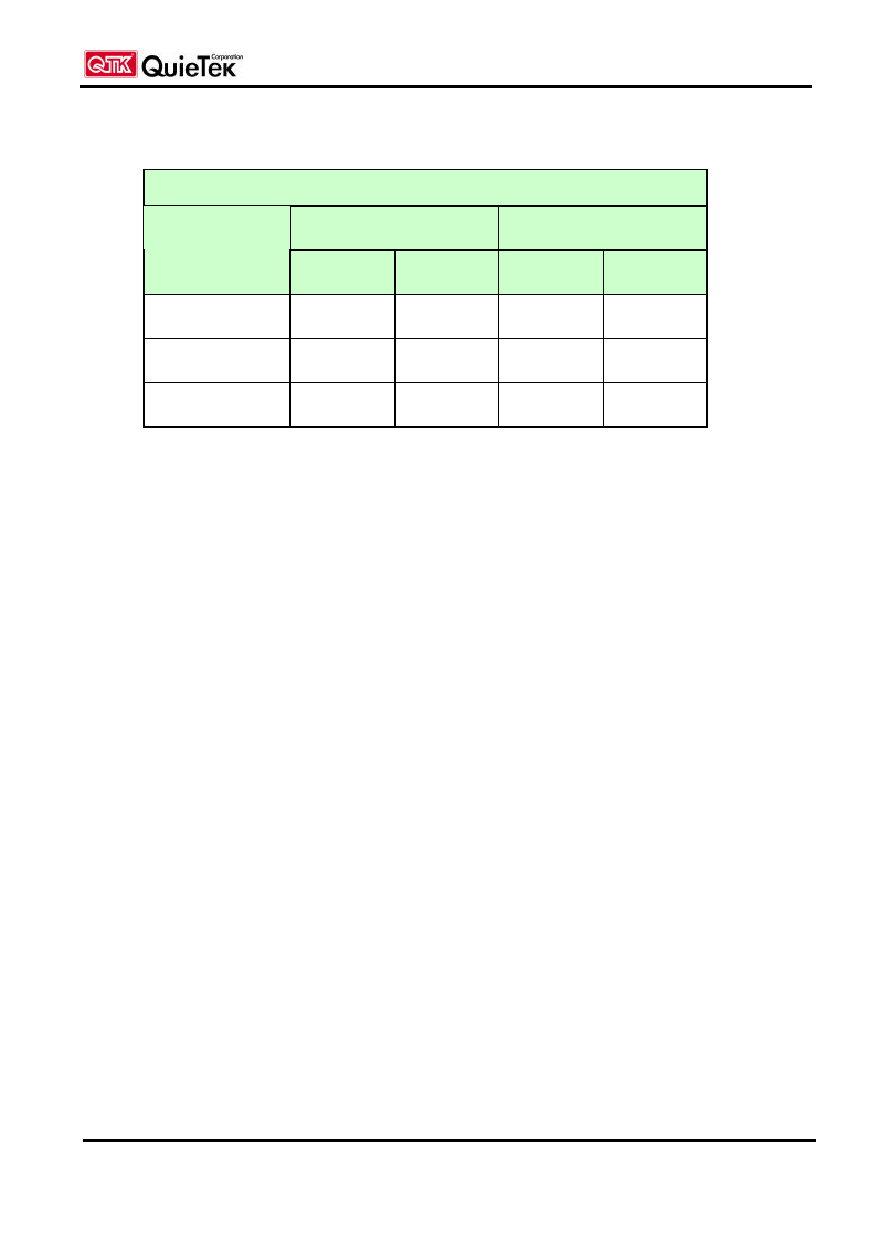
EN 55022 Limits (dBuV)
Class A
Class B
Frequency
MHz
QP
AV
QP
AV
0.15 - 0.50
79
66
66-56
56-46
0.50-5.0
73
60
56
46
5.0 - 30
73
60
60
50
Remarks :
In the above table, the tighter limit applies at the band edges.
2.4.
Test Procedure
The EUT and simulators are connected to the main power through a line impedance stabilization
network (L.I.S.N.). This provides a 50 ohm /50uH coupling impedance for the measuring
equipment. The peripheral devices are also connected to the main power through a LISN that
provides a 50ohm /50uH coupling impedance with 50ohm termination. (Please refers to the block
diagram of the test setup and photographs.)
Both sides of A.C. line are checked for maximum conducted interference. In order to find the
maximum emission, the relative positions of equipment and all of the interface cables must be
changed according to EN 55022:1998 on conducted measurement.
Conducted emissions were invested over the frequency range from 0.15MHz to 30MHz using a
receiver bandwidth of 9kHz.
2.5.
Test Specification
According to EN 55022:1998
2.6.
Test Result
The emission from the EUT was below the specified limits. The worst-case emissions are shown in
section 13. The acceptance criterion was met and the EUT passed the test.